Creating the MPE LiDAR Midi Interface
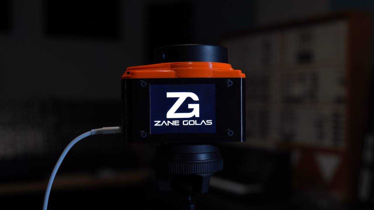
The prompt given to us for our final project in Interface Design I at CalArts seemed simple enough. We needed to "create a new musical performance interface using some sensors and a microcontroller," but all the other details were up to us.
I decided that the first logical step would be to go shopping for sensors, hoping to find something that would spark an idea. When I came across a relatively affordable 360º LiDAR package, I immediately envisioned a device that could translate positional data into music. The range and accuracy would lend itself well to sound installation pieces. Still, I was even more intrigued by the possibility of implementing the Multi Poloyphic Expression(MPE) standard, which would allow multiple people to play it simultaneously. Having found my spark of inspiration, I wrote out the following design goals for my project pitch:
- Expressive interface that can be interacted with by a group of people regardless of prior experience
- Plug-and-play compatibility with standard music software
- All data processing completed on the device
- Customizable for different end-user needs
- Compact and portable with an easy mounting system
- Use easy-to-source hardware and open-source all custom designs
- Long-term system stability for use in installations
After getting the green light on my project proposal, I ordered the sensor and pulled a Teensy 3.5 microcontroller out of the Robotic Monochord I made last year in the hopes that I could at least start working on the MPE implementation without any delays. MPE proved easy enough to code as the standard splits each voice onto its own midi channel, and then Ableton will sort it out for you as long as MPE mode is enabled in preferences. This checked off the "expressive" part of my first goal.
I firmly believe that your creative tools should try to be as stress-free and seamless as possible. Plug-and-play compatibility was needed so that artists could focus on the end result instead of trying to troubleshoot a secondary program for data interpretation. This informed my decision to pick the Teensy, as the built-in Class-Compliant USBMidi host capabilities are robust and easy to work with. They also have an order of magnitude more processing power than the commonly used Arduino, so I thought on-device point cloud processing was easily achievable.
When the LiDAR sensor arrived in the mail, I was naively optimistic. I started hooking everything to a breadboard to get the data acquisition code working... and that's when things went catastrophically wrong. I wanted a debug display on the device so I wouldn't tie up the USBMidi capabilities with a serial output on the same cable. I pulled out a cheap I2C Monochrome LCD from a parts kit, started it up, and then tried to read out the LiDAR sensor hardware buffer but got no response. After half a day trying to figure out if I had messed up the sensor's library implementation or just received a bad unit, I found a forum post that suggested the library for the display I had connected could cause errors with other UART devices. Sure enough, after removing the LCD and its associated library, I got LiDAR data to print out in the console. Crisis averted.
I took this setback as a sign that I should upgrade to a small TFT color touch screen since doing everything on the devices would require a way for users to make adjustments on the fly. Adding this made me concerned about the Teensy 3.5's ability to keep up, so I bought a Teensy 4.1 and decided to stick with that choice for the final design. After a lot of code and a few settings tweaks, I finally had a janky version propped up on a cardboard box playing Serum.
This worked well enough for a single person with a cardboard box, but the clustering algorithm quickly lost its ability to distinguish objects if they came too close. Since I wasn't well versed in this area, I decided to give myself a crash course in Data Science and ultimately implemented the more powerful DBSCAN method. This wasn't without cost in latency performance, so I decided to make a user-selectable toggle between the two modes, allowing for 0-1ms of latency using the older method and 18-22ms of latency when precision was required. At this point, I felt comfortable enough with the reliability to start working on the physical case design.
Physical Design
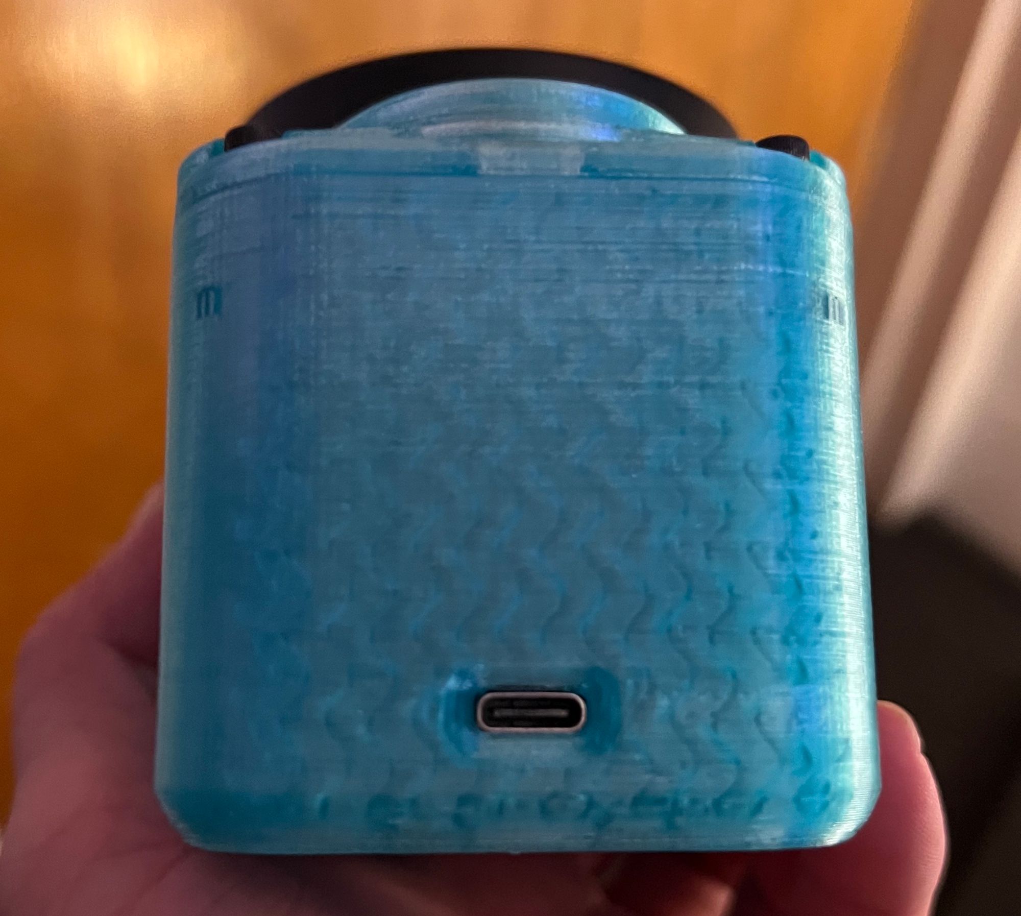
The RPLiDAR has a very cool swept footprint, so I imported an STL from the manufacturer to Fusion 360 and built off of it for inspiration. At this point, I should mention that I have a deep hatred for micro USB ports due to their complete lack of durability. This led me to choose USB-C as a balance between compact design and ruggedness.
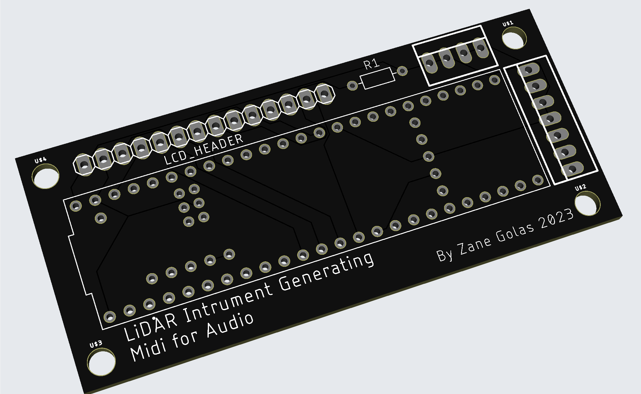
To further increase the reliability and repairability, I designed a custom breakout PCB so cables would stay neat and could be detached easily for component replacement.
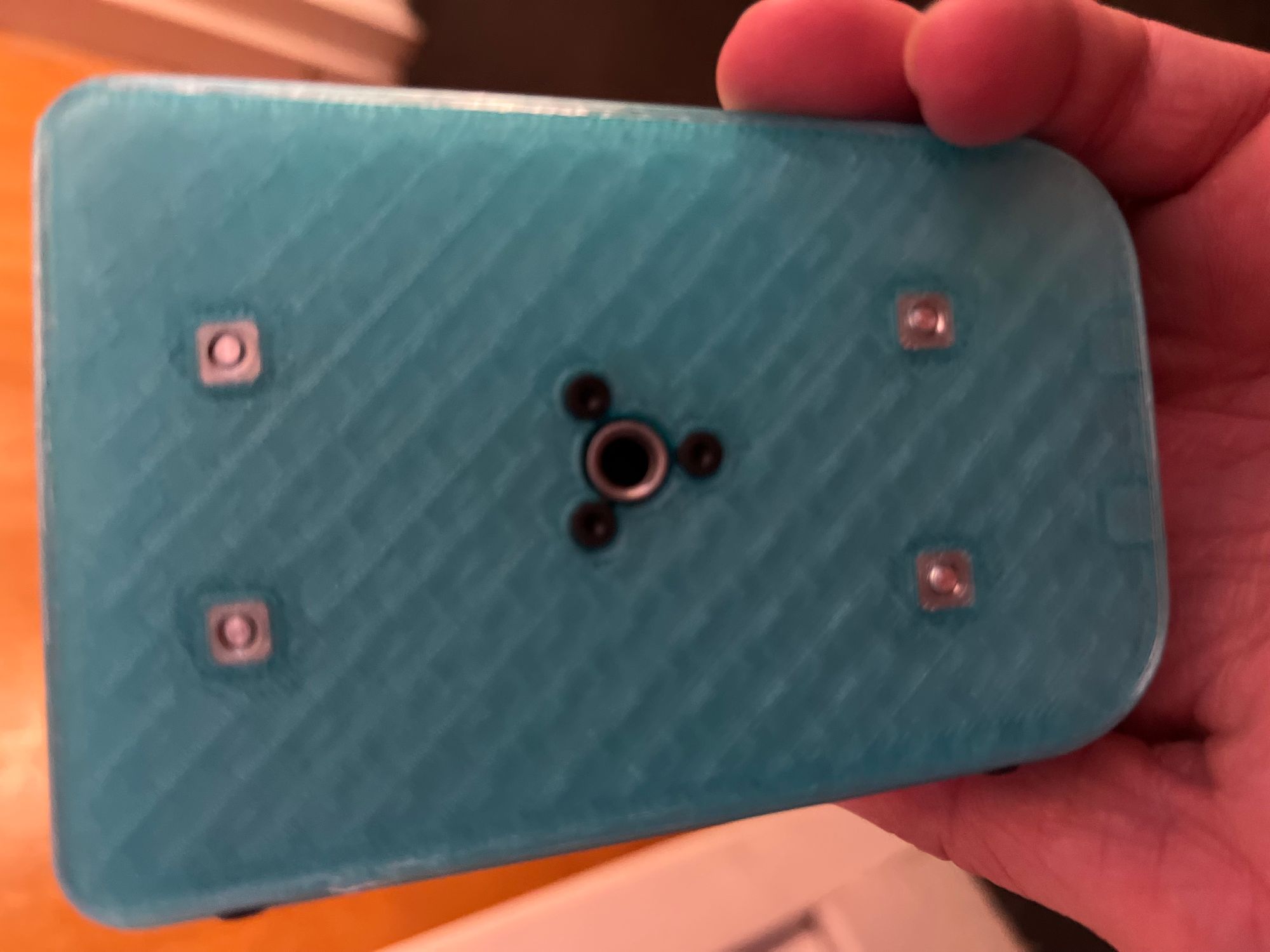
The final missing piece in the case design was a mounting system. Adding a standard tripod thread hole seemed like the obvious choice for maximum compatibility, but the premade baseplates I initially saw were bulky and expensive. Instead, I decided to flip a screw mount nut upside down in the unit's base, which worked surprisingly well.
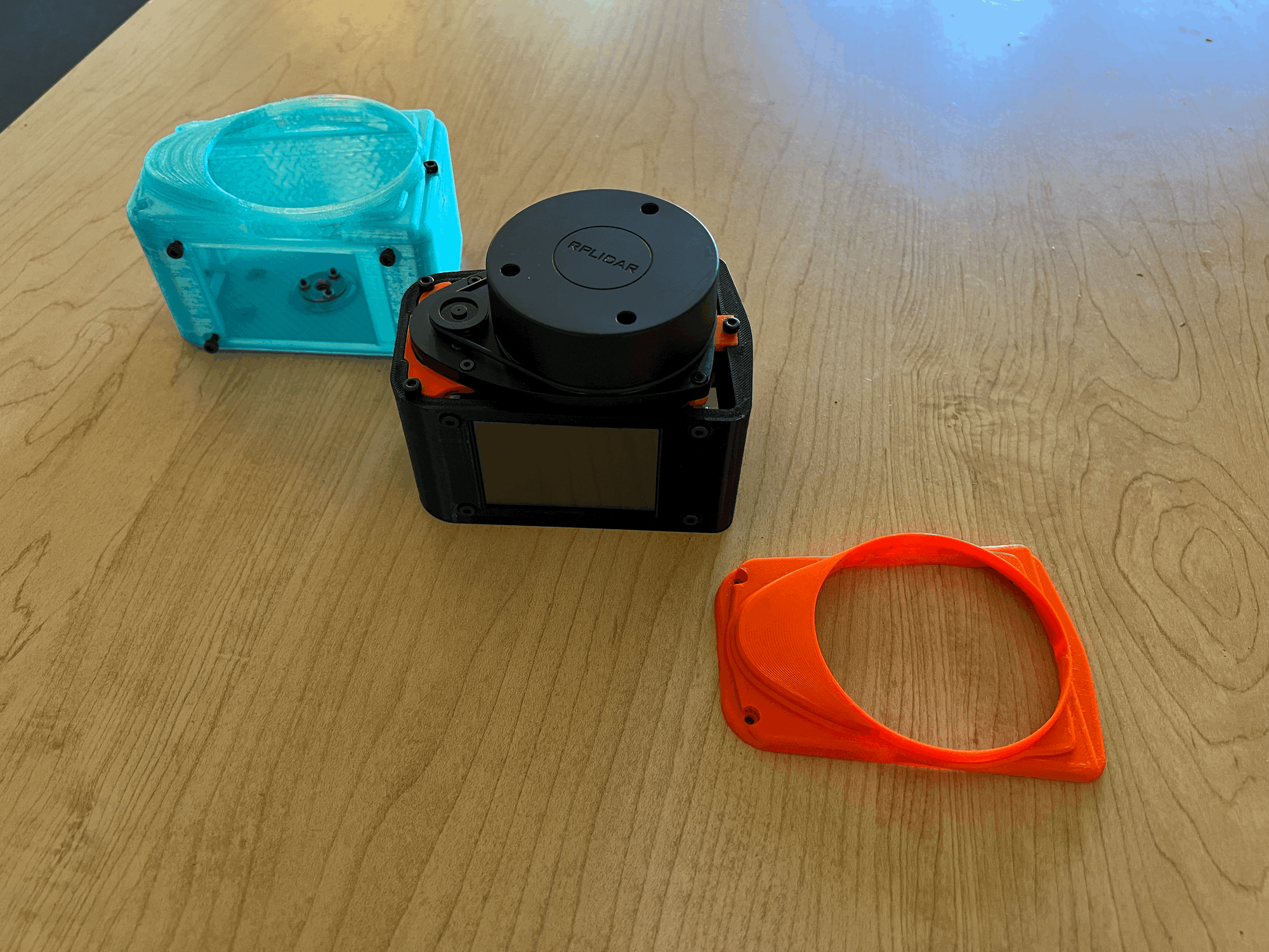
When it came to actually printing the design out, I experimented with print orientation, support types, tolerances around moving parts, and pauses between layers to insert captive nuts. It was a long process, but the result was sleek, with a good amount of strength and minimal cosmetic damage caused by the tree supports.
Finishing Touches
It was now time to turn my attention back to the code. I decided to make the default display state show the objects being tracked in the center with quick settings info in the corner. A settings menu can be opened by clicking the gear icon in the bottom right corner. I made a quick cyberpunk-inspired UI mockup in Figma and implemented it in the code. If I'm being honest, this part will probably need the most work in the future as the menu system is hacked together on the skeleton of an open-source library that was never meant to be used this way.

After many more tweaks to debug and some longer duration runs, I had finished two days before our final presentations were scheduled, so I decided to take some inspiration from the Microsoft Surface Studio Reveal trailer and make a fun teaser video...
Unfortunately, my ambition for the video far exceeded my skills in 3D animation, so I had to take a more creative approach, as seen in this exclusive behind-the-scenes video...
As much fun as I had with all of that, the most rewarding part of this process was exhibiting it at the CalArts expo and watching how people interacted with it. The excitement was contagious, and the amount of interest I received from other artists to include this in their work serves as an excellent motivation to continue development.
